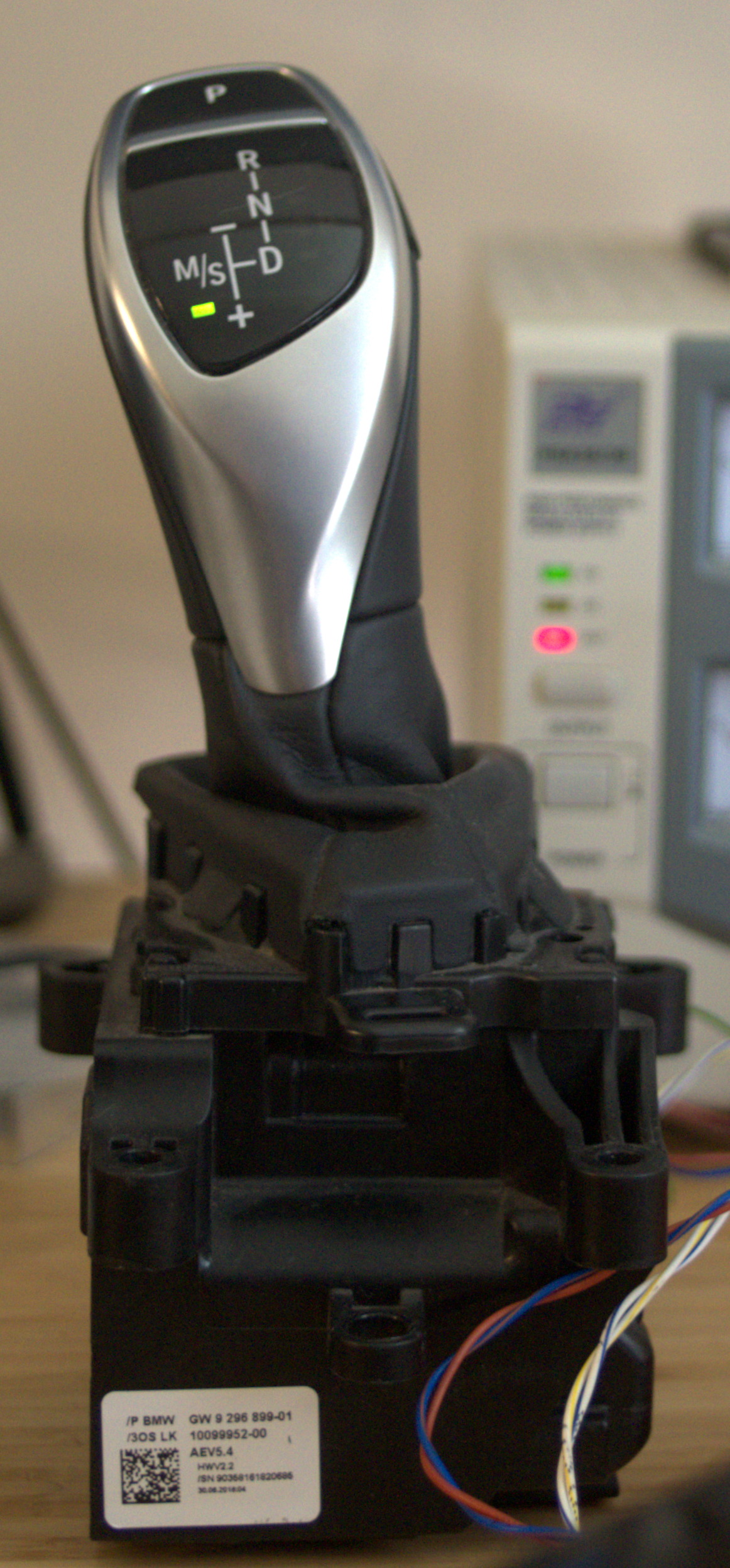
This is the third and final post about adapting this 2014 BMW F20 GWS (automatic gear selector) for eventual use in an Electric Vehicle conversion:
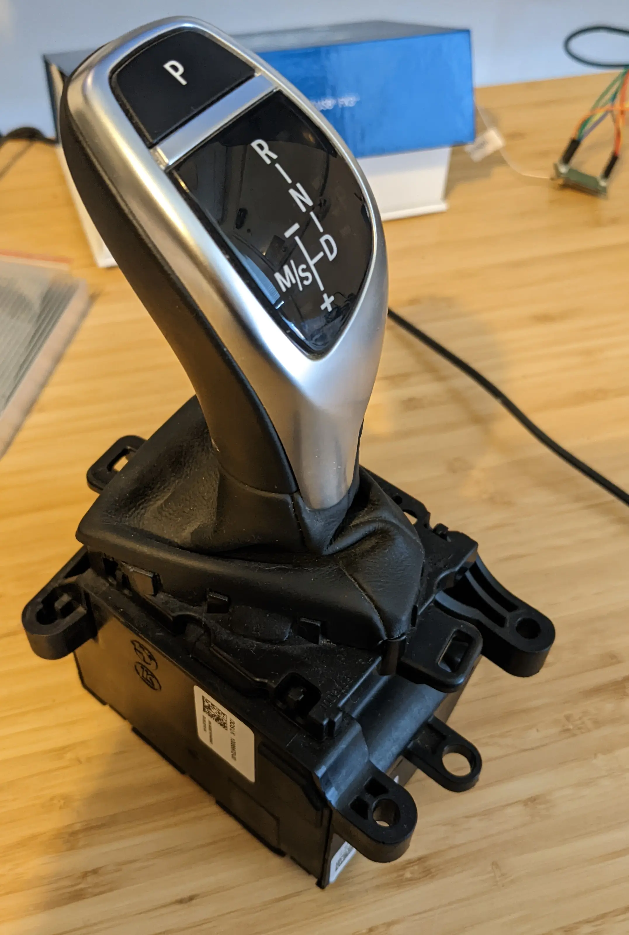
In Part One I got the GWS wired up and received some CAN messages from it. Without access to a whole car I had no success finding messages to send back to it, though.
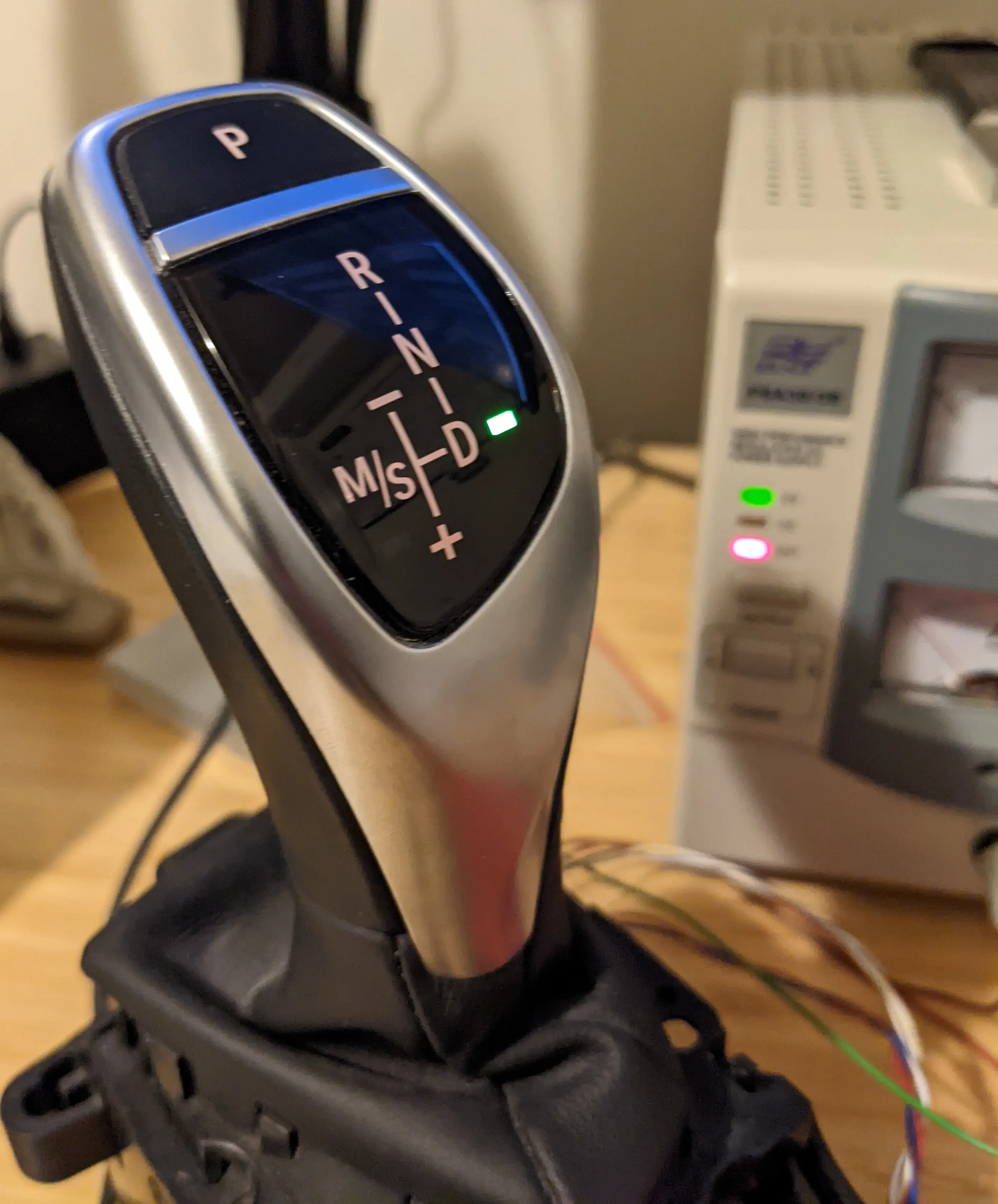
In Part Two I figured out those messages, particularly CAN ID 0x3FD which has the state of the transmission. By the end I could get the GWS to behave as if it was talking to a real automatic transmission:
Here's the reverse engineered structure of the 0x3FD message that would be sent by the transmission controller (EGS) to the GWS, if I had an automatic transmission:
| Byte | Meaning |
|---|---|
| 0 | CRC8 of bytes 1-4 (init=0x0, poly=0x1d, xor=0x53) |
| 1 | Counter value (must increment each message) |
| 2 | Payload byte 0 |
| 3 | Payload byte 1 |
| 4 | Payload byte 2 |
Counter gotcha
At this stage, sending valid 0x3FD messages worked great except for this one weird glitch, the LED would blink out very briefly and then come back:
If the GWS is in Drive mode, it even caused the lock motor to make a buzzing noise as the light blinked out.
Watching the CAN messages scroll past, I realised that any counter value ending in 0x0F was considered invalid and the GWS was treating it as an error.
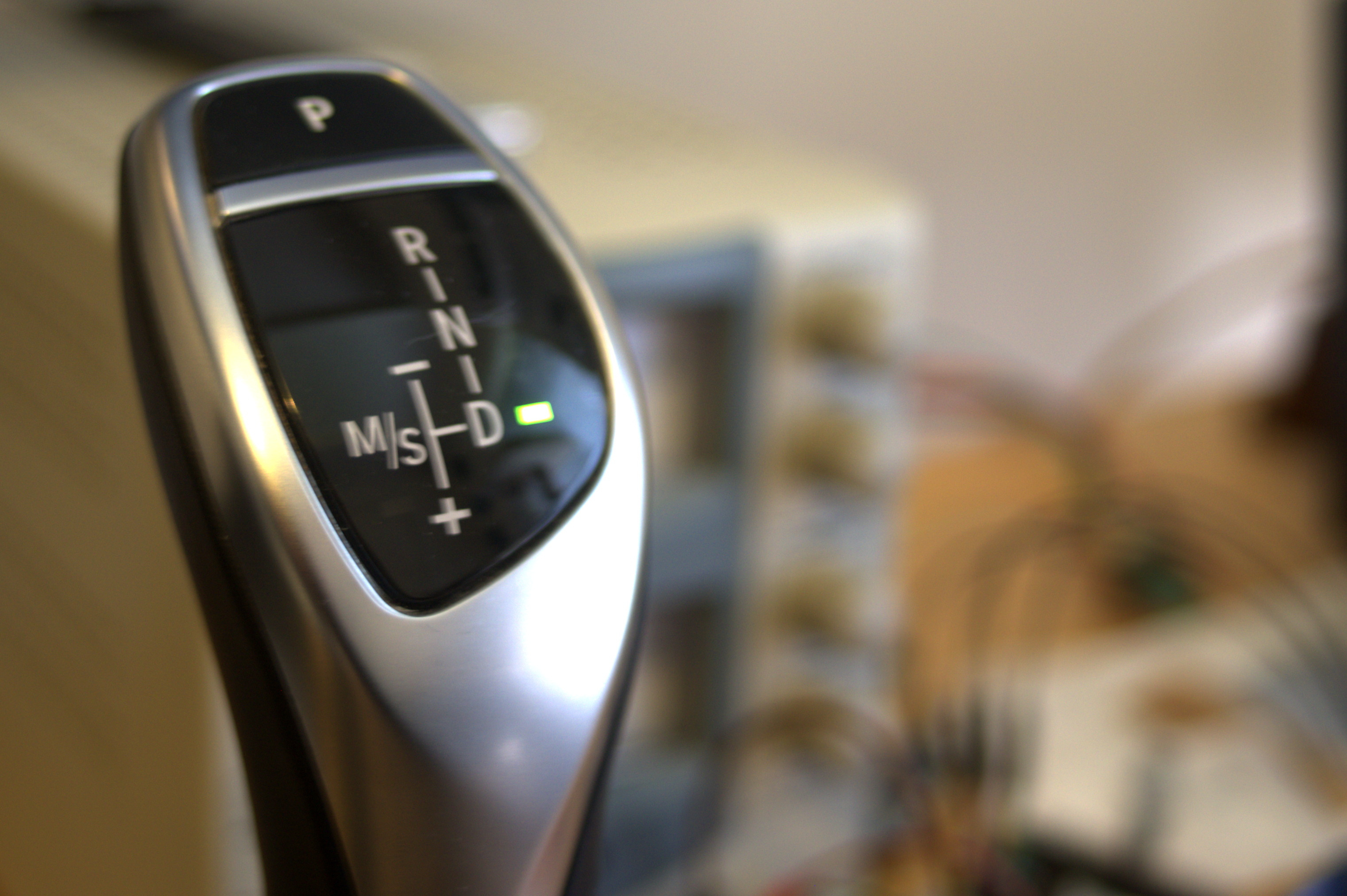
It became buttery smooth after a small tweak to skip counter values ending in 0x0F:
On Twitter, @rndashm explained: ECUs will set "invalid signal" or "missing signal" to all-1s in the CAN message fields. So the counter is probably 4 bits wide (possible values 0x0-0xF), and value 0xF means "missing" (most likely, the CPU has never written this field).
Payload Bytes
Randomly changing payload bytes, sending a sequence of messages to the GWS, and writing down the behaviour was enough to find most of D,N,R,P etc. It seems like the whole shifter state can be controlled by setting byte 0 of the 3 byte payload:
| Payload byte 0 | Display |
|---|---|
| 0x00 | Blank gear selection (appears off) |
| 0x20 | P |
| 0x80 | D |
| 0x81 | D, can move to M/S |
| 0x81 | M/S (if lever moved to side) |
| 0x40 | R |
| 0x60 | N |
| + 0x08 | To flash the selected gear light |
The other two bytes in the payload can be zero. Best guess, these are parts of the transmission status that the GWS doesn't care about (for example the exact number of the current gear). If you have a BMW with one of these transmissions and shifters, please feel free to point out a GWS function that I've missed!
The GWS has some internal control logic and changes behaviour depending on the selected gear. For example, if the transmission is Park then it will still allow the driver to push the lever back and forward but it won't report this movement unless the Unlock button is also held down.
Moving from "D" to "manual and sport" mode ("M/S") is done by the driver pushing the lever to the side. It's only physically possible to do that if the GWS is in "D". The byte value should also be 0x81, if it's set to another value then the lever moves itself back to the centre automatically.
Building a UI
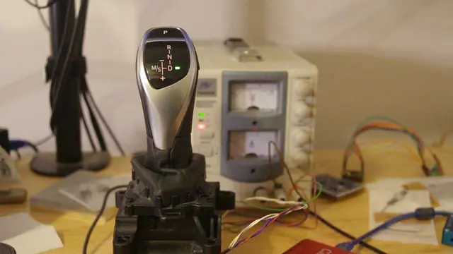
The "Bavariatron 5000" is a small GUI application to talk to the GWS from a desktop computer and emulate an automatic transmission in a car. I used this to finish figuring out the status messages and make sure I could control all of the GWS states:
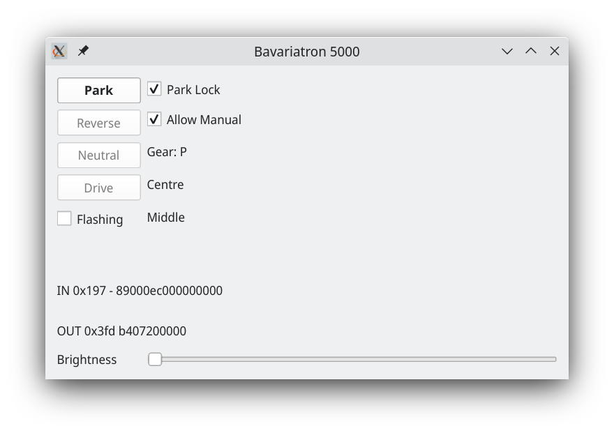
It works pretty well, aside from the whole "no car" part:
Many "features" of the GUI are implemented all in the desktop software, by responding to (or not responding to) gear input and changing the state of the GWS. This includes all mode changes, manual gear selection, "Park Lock", and responding to the Park button. There's a lot of room here to make wacky gear selectors that do totally unexpected things, but for now I'm trying to reproduce what the original car had.
Debugging the GUI helped flesh out the status values in the 0x197 message sent by the GWS:
| Status message Byte | Meaning |
|---|---|
| 0 | CRC8 of bytes 1-3 (poly=0x1d, init=0x0, xor=0x53) |
| 1 | Counter value, 4 bits wide, should change each message, never 0x0F[*] |
| 2 | Lever position |
| 3 | Park button (0xC0 normally, 0xD5 if Park is pressed) |
[*] The upper 4 bits of byte 1 are usually zero, but they become non-zero when the lever is in the side position. This is probably a firmware artefact though, as the same information seems to be in byte 2 as well.
The lever position byte values are:
| Value | Meaning |
|---|---|
| 0x0E | Centre middle |
| 0x1E | Pushed "up" (towards front of car) |
| 0x2E | Pushed "up" two notches |
| 0x3E | Pushed "down" (towards back of car) |
| 0x4E | Pushed "down" two notches |
| 0x7E | Centre side |
| 0x5E | Pushed "side and up" |
| 0x6E | Pushed "side and down" |
Given the lower nibble is always 0xE then it's possible this also signals something else that I haven't changed, but I don't know what that would be.
Other Message IDs
Keen readers may have noticed in Part Two that the GWS also reports DTCs related to some other CAN messages:
| DTC | Meaning |
|---|---|
| E09408 | No message (terminals, 0x12F), receiver GWS (PT-CAN), transmitter BDC (PT-CAN) |
| E0940C | No message (LCD brightness control, 0x393), receiver GWS (PT-CAN), transmitter KOMBI (PT-CAN) |
| E09420 | No message (relative time, 0x328), receiver GWS (PT-CAN), transmitter KOMBI (PT-CAN) |
| E09422 | No message (vehicle condition, 0x3A0), receiver GWS (PT-CAN), transmitter BDC-ZGM (PT-CAN) |
What are these for, if everything already works?
I don't know, but I think it's to help diagnose CAN bus issues: if there's an intermittent fault in PT-CAN then having each module report which other modules are disconnected may be really useful. Probably other uses too, for example synchronising "relative time" allows correlating "freeze frame" DTCs between modules to find which system faults happened at the same time.
However, none of these messages seem to be necessary for the GWS's normal functions.
Reflection
It's satisfying to gradually find scraps of information and loose threads, and pull on those threads a little at a time. Usually it doesn't make much difference, and can feel like a waste of time and effort. Occasionally you learn something new that might come in handy later. Then suddenly you pull a thread and the whole piece unravels in front of you. I hope this came across in Parts One and Two, I reckon it worked out really well here.
There were invaluable clues in random pieces of information found online, such as DTCs and descriptions of protocols. Other people had posted these on web forums for their own reasons, but I'm very thankful to them! In a more sensible society, Right To Repair legislation would make it mandatory for manufacturers to publish this kind of information - they already have this all documented internally, and it'd potentially give these components (and cars) longer and more useful lives than they currently have. Nevertheless, as seen here, it can be possible to piece together a lot from information already online.
Some details made this task particularly easy, for example how the BMW DTCs included the actual hexadecimal CAN IDs in the description. Probably a little more "thread pulling" could have gotten this information even if it wasn't published: once you can read the active DTCs then seeing one that goes away or changes when you send a certain CAN message will pretty quickly help you work out which messages relate to which DTCs. You can keep "pulling the thread" to figure out DTC meanings and valid/invalid messages this way.
An even more generalised lesson, DTCs are an example of the "debugging side channels" that can be gold mines for otherwise hidden information about a system.
Worth it?
From a less optimistic angle, this was a bunch of work to find what ended up being a total of 3 data bytes to control six LEDs and read the position of one lever and two buttons. A very nicely made lever, but still... I'm curious about trying this approach on something more complex.

Of course, characterising the GWS as "3 data bytes" or "six LEDs" also glosses over a lot of BMW's engineering. Unlike reading a simple joystick or a set of buttons, the transmission can differentiate fault states or errors from valid GWS output, and will not read transient invalid output (like "switch bounce") when the lever is moved. The GWS can refuse invalid or unsafe driver input, and is designed in a way where the transmission can switch modes without any mismatch between what the driver sees and the real state of the system (for example, the car can automatically engage Park). Selecting gears in a car is a safety-critical task with the potential to cause a lot of injury if the gear state is misunderstood or incorrectly controlled, so all of this is valuable. Despite being much more complex and electronic, the BMW GWS unit has clearly been engineered with a goal of being as predictable and failsafe as a manual mechanical shifter or selector lever.
Finally, this project has been pretty fun to work out and write up - a key factor given that this is a hobby.
That's it?

I haven't written any actual firmware that talks to the GWS: only experimental Python code and the test GUI that runs on a desktop computer. The obvious next step would be to integrate this in some kind of VCU (Vehicle Control Unit) firmware that drives an EV around.
I might not do that, because as it happens my EV plans have changed enough that I might not need this kind of lever. Oops! Will write more about that, soon. Hopefully these experiments are still useful for someone else.
All of the experimental functions described in these posts, plus the UI program, can be found here in this car_hacking repo of random experimental code. There is also a wiki page on openinverter now (thanks @Crasbe) that may pick up more details as time goes by.
Please leave a comment if you build something with one of these, or if you try talking to a different but similar BMW GWS.
Thoughts on “BMW F Series Gear Selector, Part Three: Success”