I'm overdue to write up some of my vague electric vehicle conversion project, so here's a small part of it.

Note: This post is a journey through the awkward process of reverse engineering. If you're here to find out what CAN messages control a BMW F series GWS module, skip this post and read the later parts.
Shifting Gears
My goal was to find a gear selector to suit a car converted to an EV-style "fixed reduction gear" gearbox. This is basically an "automatic transmission" but without any different gear ratios, only a fixed gear ratio and a motor that drives forward and reverse:
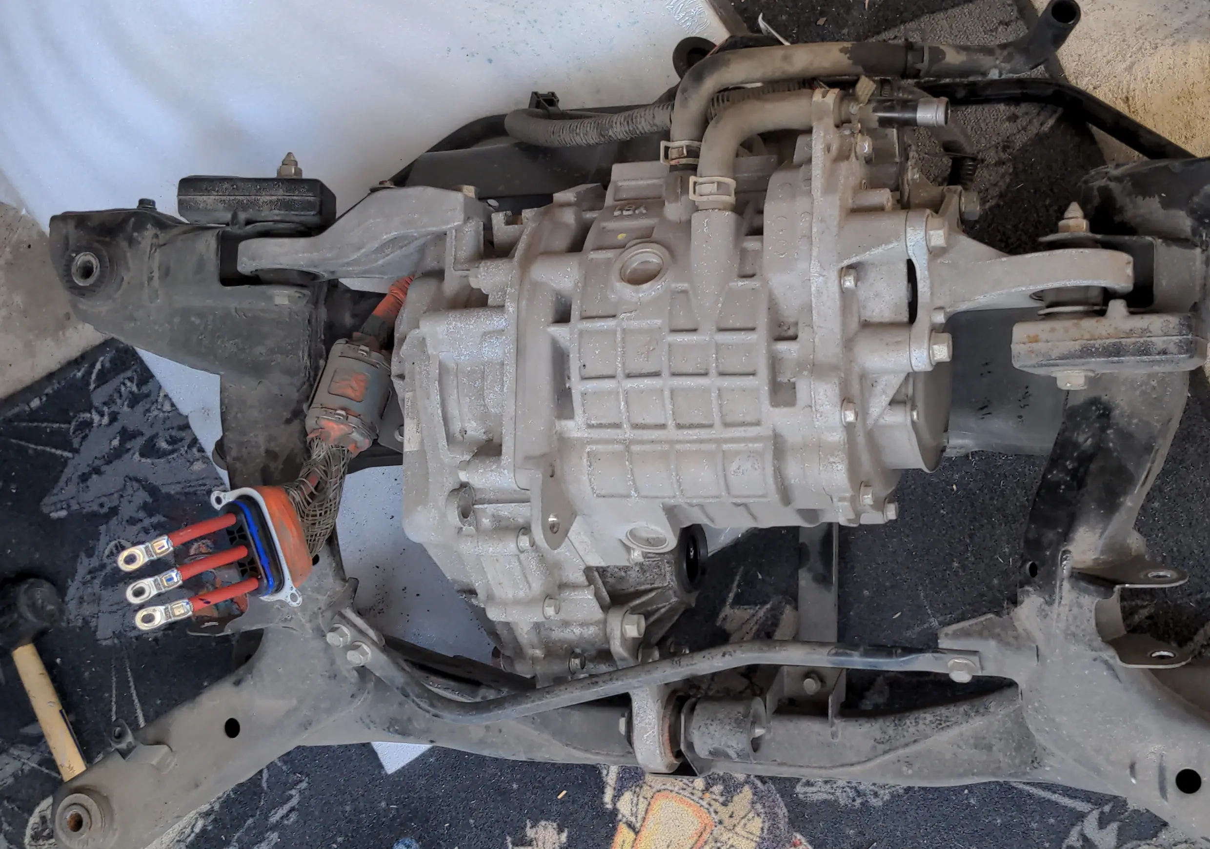
(That motor and reduction gear is from a Mitsubishi Outlander PHEV.)
Most older auto transmission gear selectors aren't great for this because they depend on a mechanical linkage to the transmission. On newer models the physical linkage may only be to get in and out of Park Lock, but on older models it can be how every "gear" is selected (Neutral, Drive, Reverse, etc.).
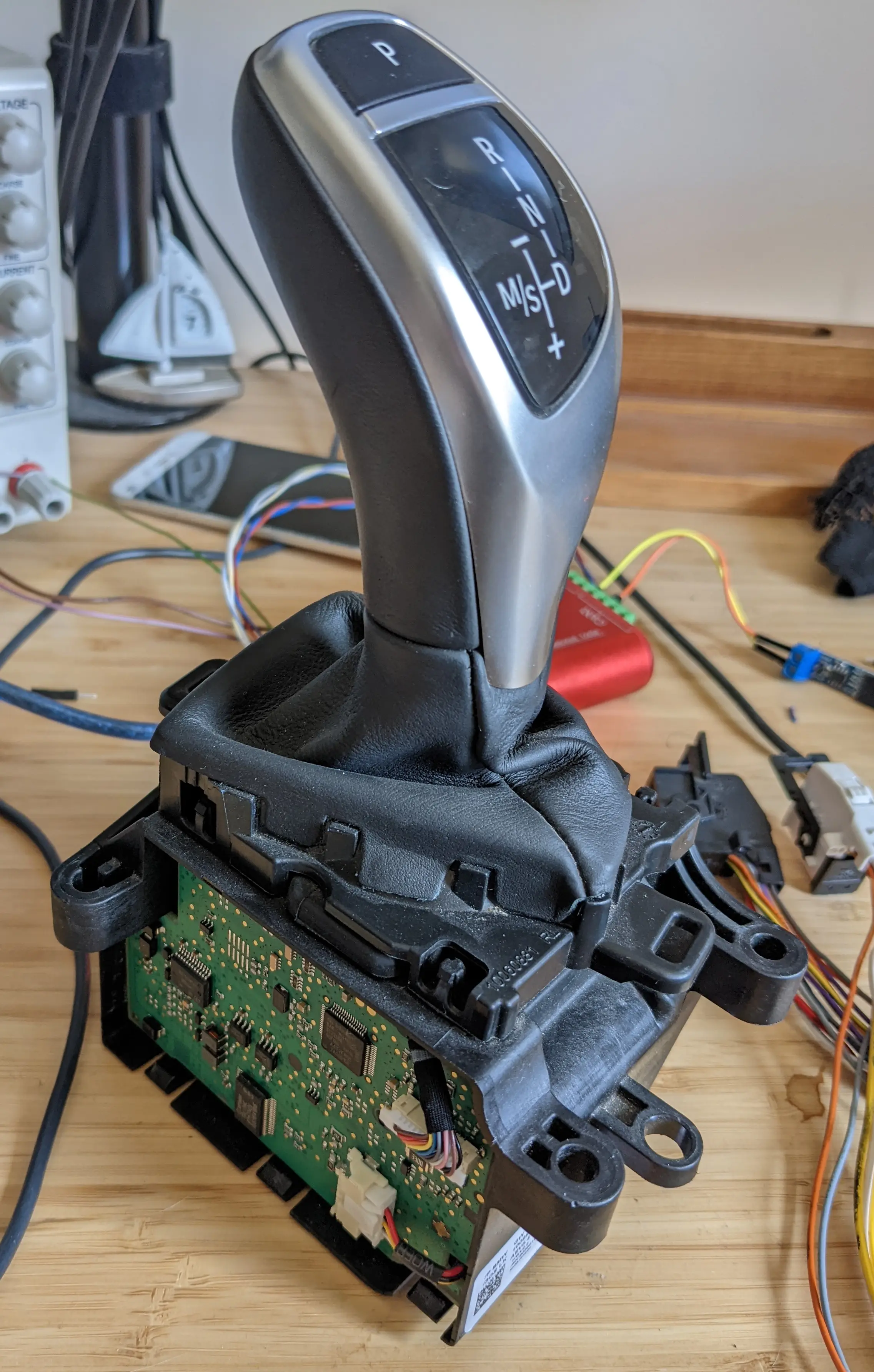
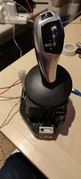
After looking at a few options that wouldn't fit, I stumbled across these really nice looking gear selectors from BMW:
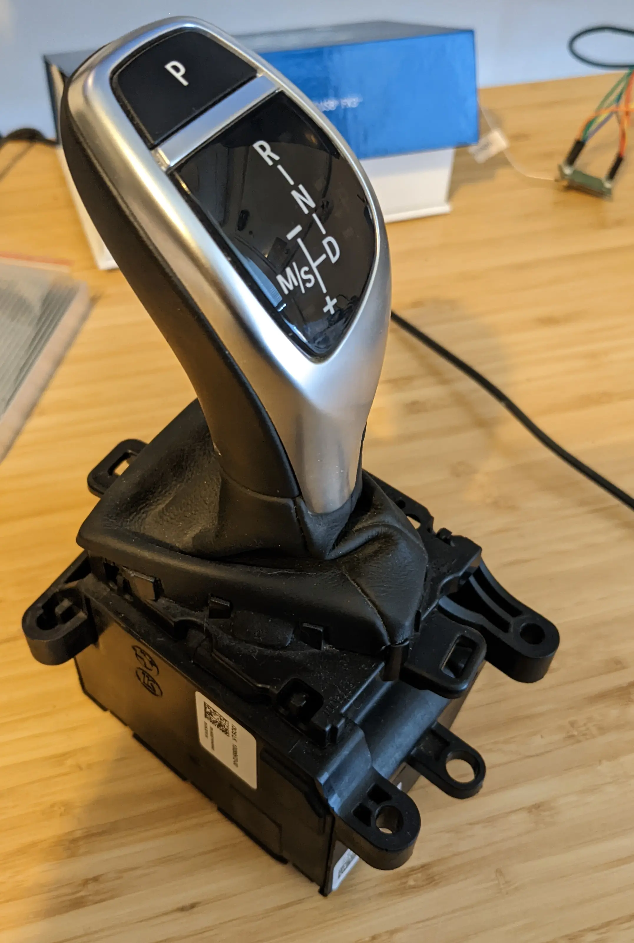
(BMW calls this a "GWS", please comment if you know what this stands for in German.)
They are fully electronic, basically a glorified computer joystick with electro-mechanical features to unlock and re-lock manual shift mode, and even to move out of that mode.
BMW North America made this video about how to use them:
Many of the "F" series model code BMWs (2008 and newer), plus some "G" series, have a version of this gear selector but the specifics vary.
The particular one I have is part number "GW 9 296 899-01"/"100999952-00":
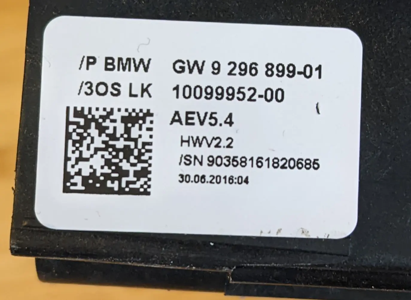
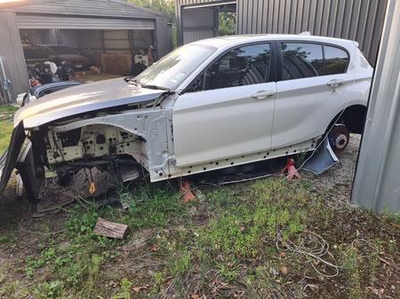
It's from an F20 model: a 2014 BMW 125i LCI that was crashed.
The person parting out this car was kind enough to give me the plug and a length of wire from the loom, which is useful because this inline connector seems pretty custom:
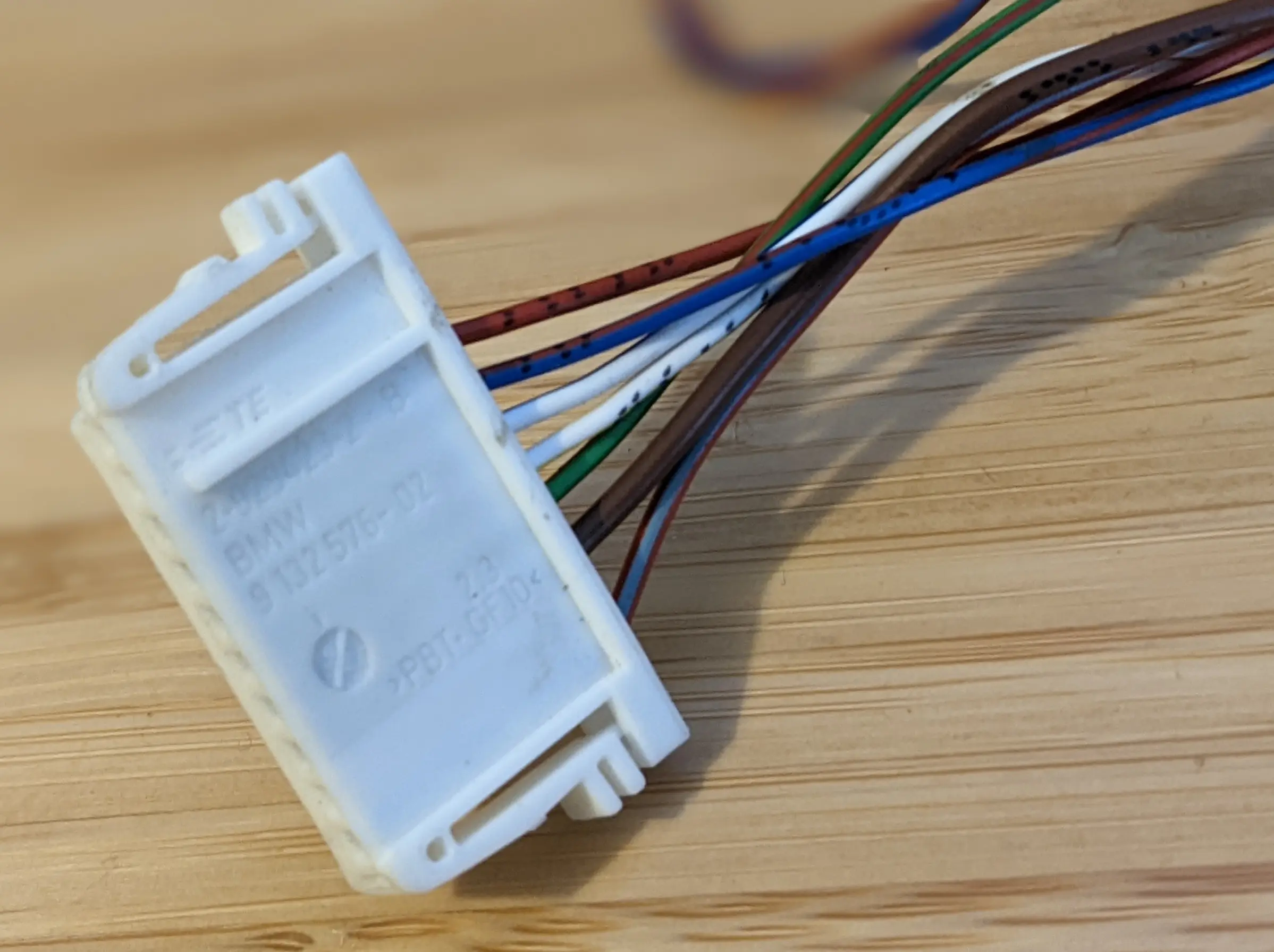
The plug is BMW part 9132576-02. It's also marked with the OEM TE part number 2-929423-2, but this comes up on the TE website as "RESTRICTED PRODUCT"...
About these selectors
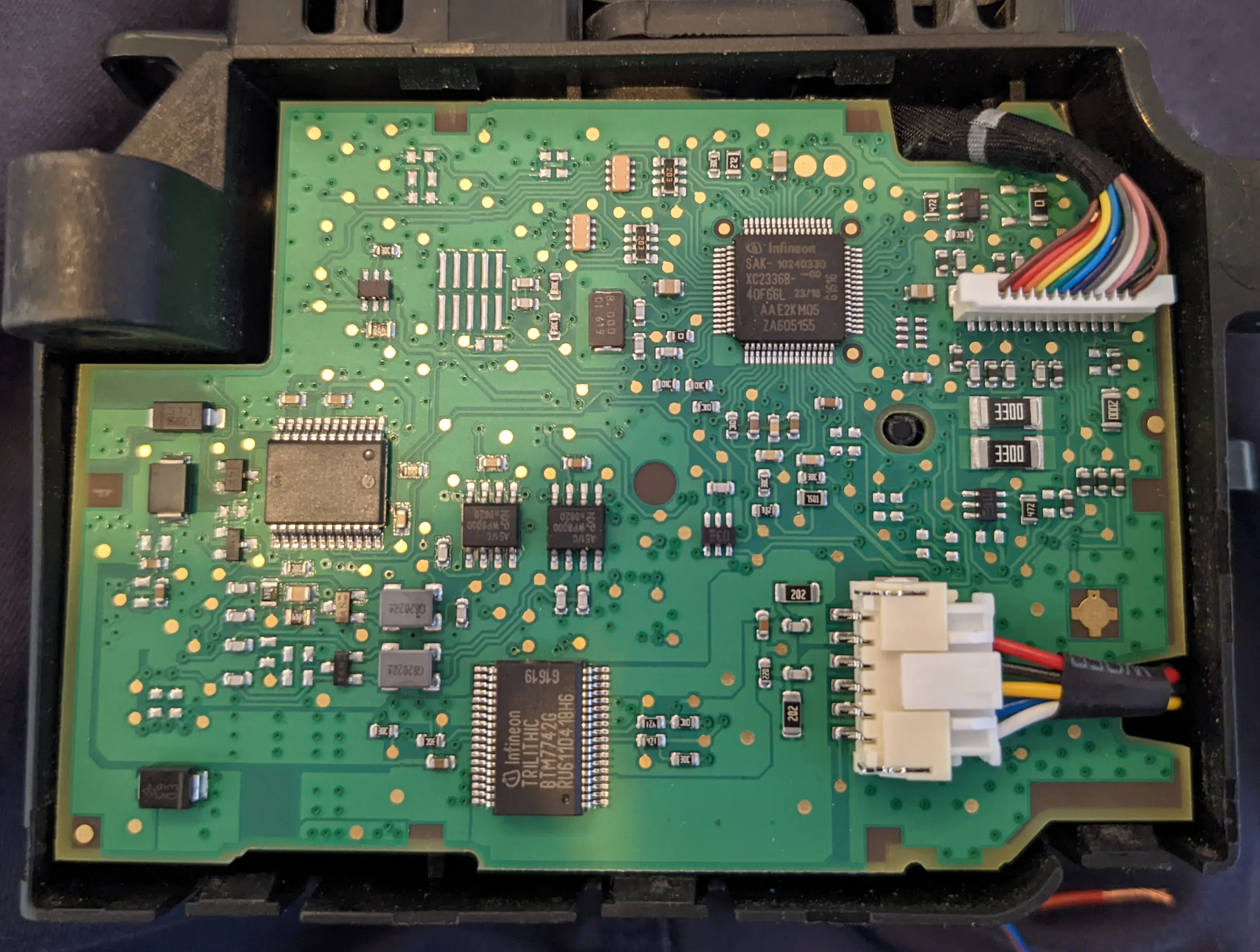
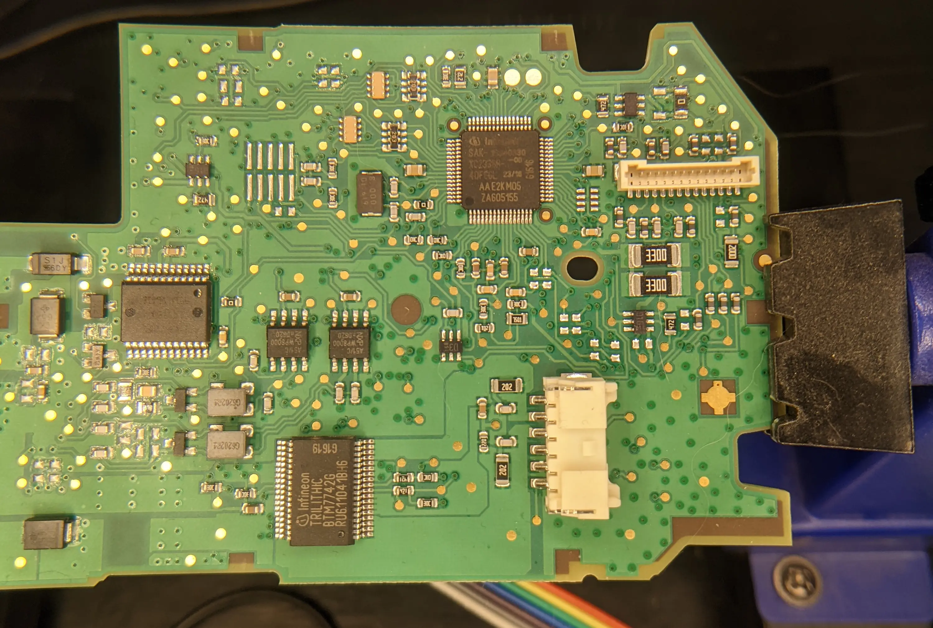
Like most automotive-grade hardware, the PCB inside this thing is pretty classy:
On the back of the PCB there's a nifty circuit that interacts with the lever movements:
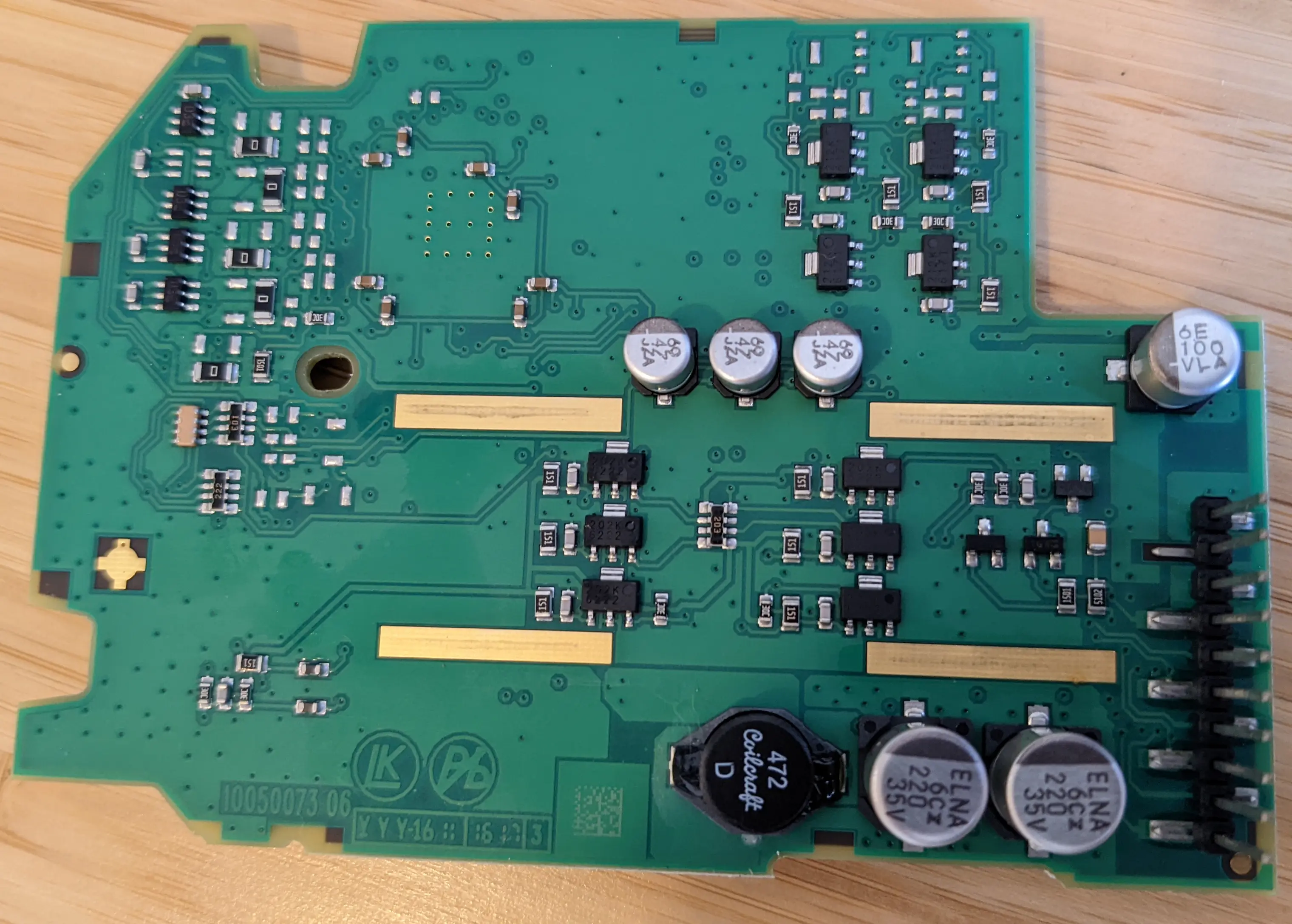
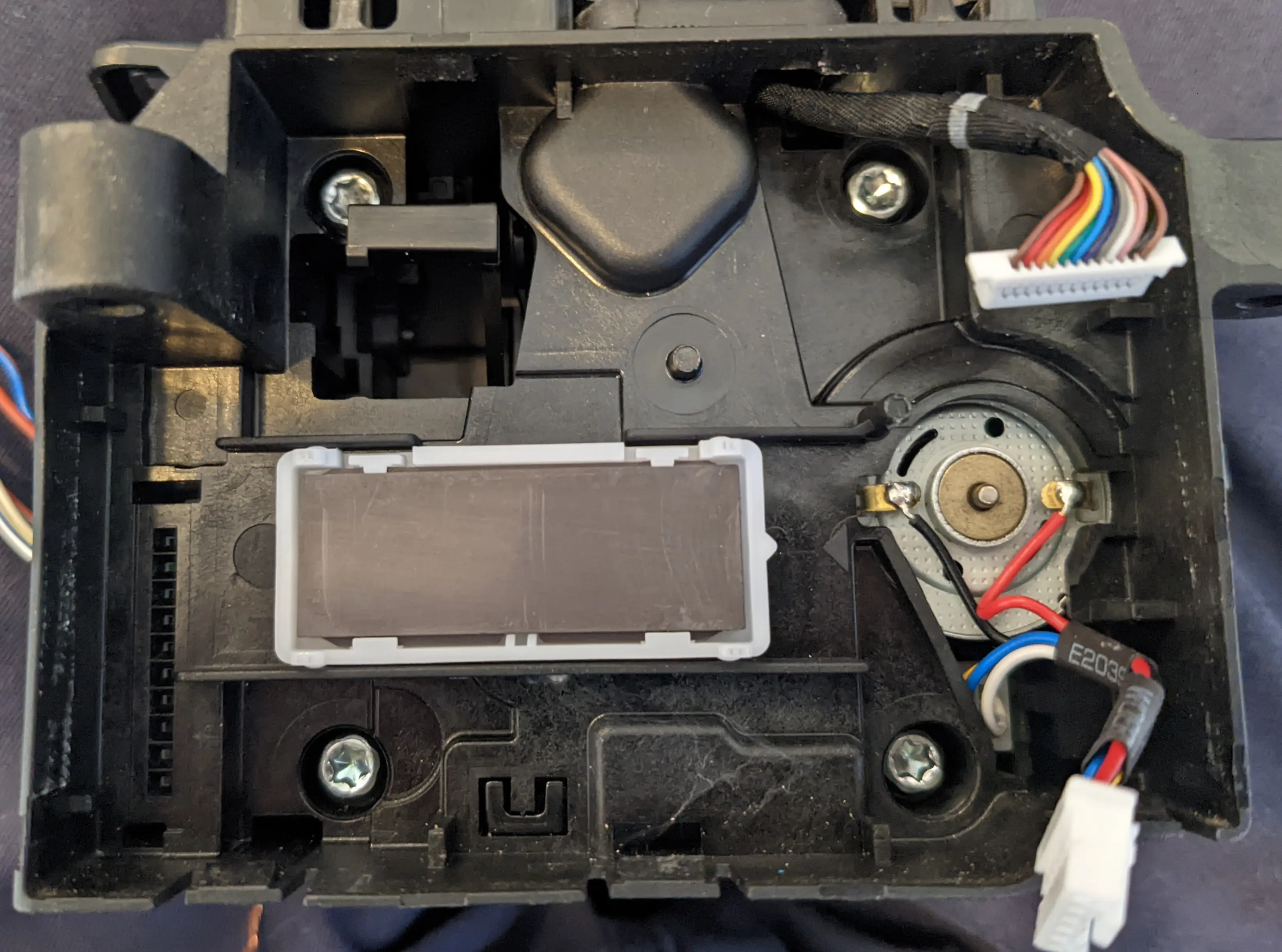
I think this circuit exists to detect movement, there's a separate motor that seems to do locking and for the GWS to move the lever.
Keeping with automotive tradition, there is also an obscure Automotive Market Microcontroller (tm) on there:

This one is an Infineon XC2336B, which actually has a public product page with a datasheet (gasp). You can even find a pinout and (maybe) download an SDK, all from the manufacturer's website. What an age we live in...
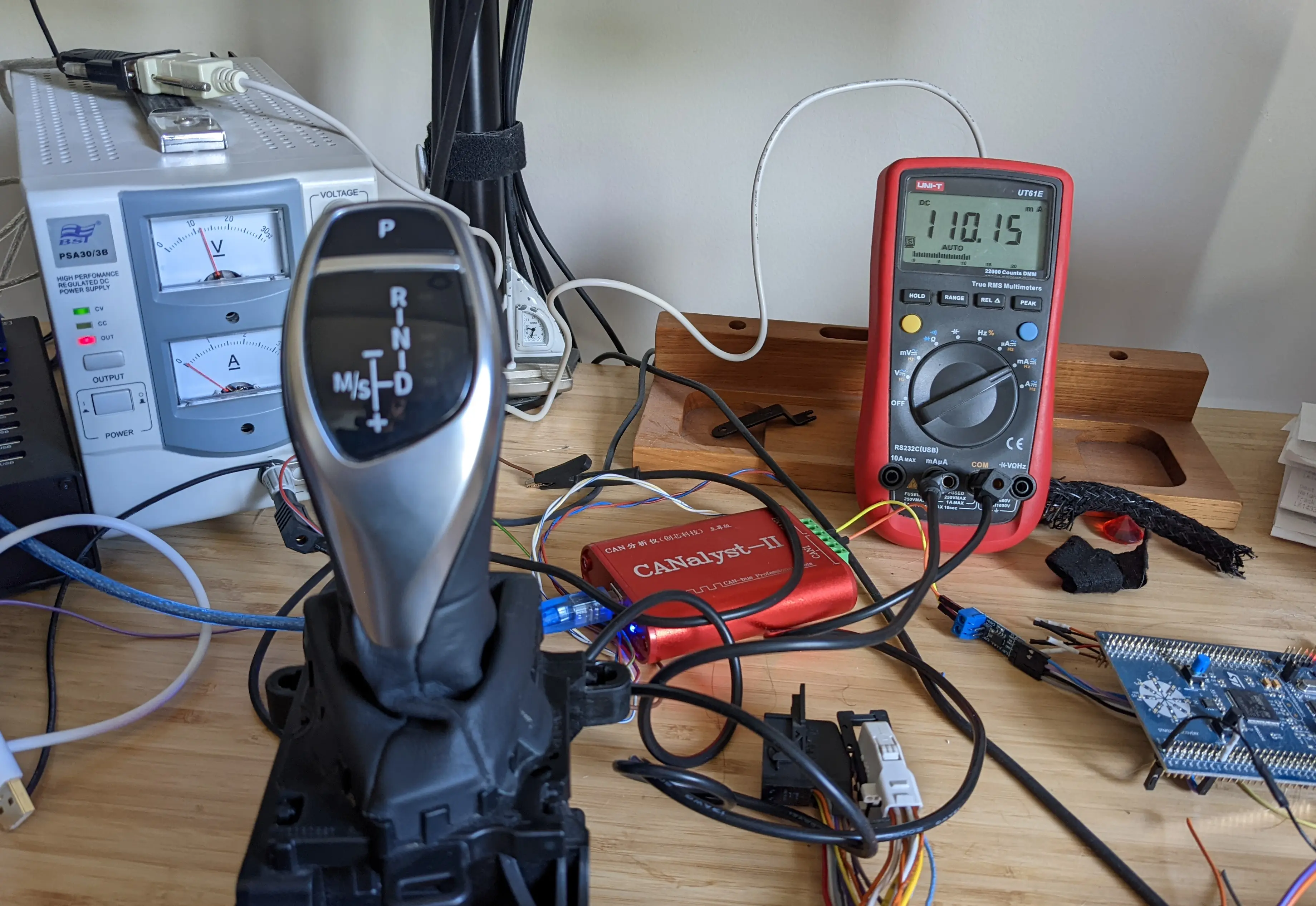
Hooking it up
First step, work out how to wire this up without cooking it...
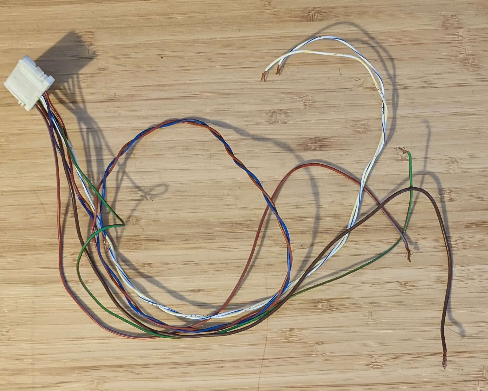
Having original wires from the loom is a huge head start:
- There are two obvious twisted pairs - those are probably CAN
- Red/blue striped and brown wires are described online as being BMW's usual colours for "Switched 12V" and Ground. A quick check on the PCB shows that the red/blue wire is diode protected against reverse polarity and feeds closely into the power section of the board, so that seems like a sure thing for 12V.
Drifting around the internet are some BMW technical documents that show how many F-series cars have two powertrain CAN buses, PT-CAN and PT-CAN2. Here's part of the diagram showing modules connected to each bus:
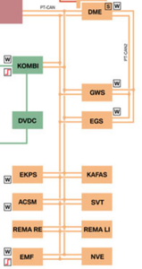
It's like the engineers said "OK, we're making another Powertrain Bus - But Only The Real Powertrain Modules are allowed this time!". The BMW documents note that PT-CAN2 is a redundant link so we can hope it carries the same messages as PT-CAN for the three connected modules (Engine controller DME, transmission controller EGS, gear selector GWS).
BMW forum posts also suggested that PT-CAN is often Red and Blue/Red wires. That identifies PT-CAN, so the other twisted pair is probably PT-CAN2:
| Pin | Wire Colour | Function |
|---|---|---|
| 1 | NC | |
| 2 | NC | |
| 3 | Red | PT-CAN Low |
| 4 | Blue/Red | PT-CAN High |
| 5 | White/Blue | PT-CAN2 Low |
| 6 | White/Yellow | PT-CAN2 High |
| 7 | Green/Brown | ??? |
| 8 | Brown | Ground |
| 9 | NC | |
| 10 | Red/Blue | +12V |
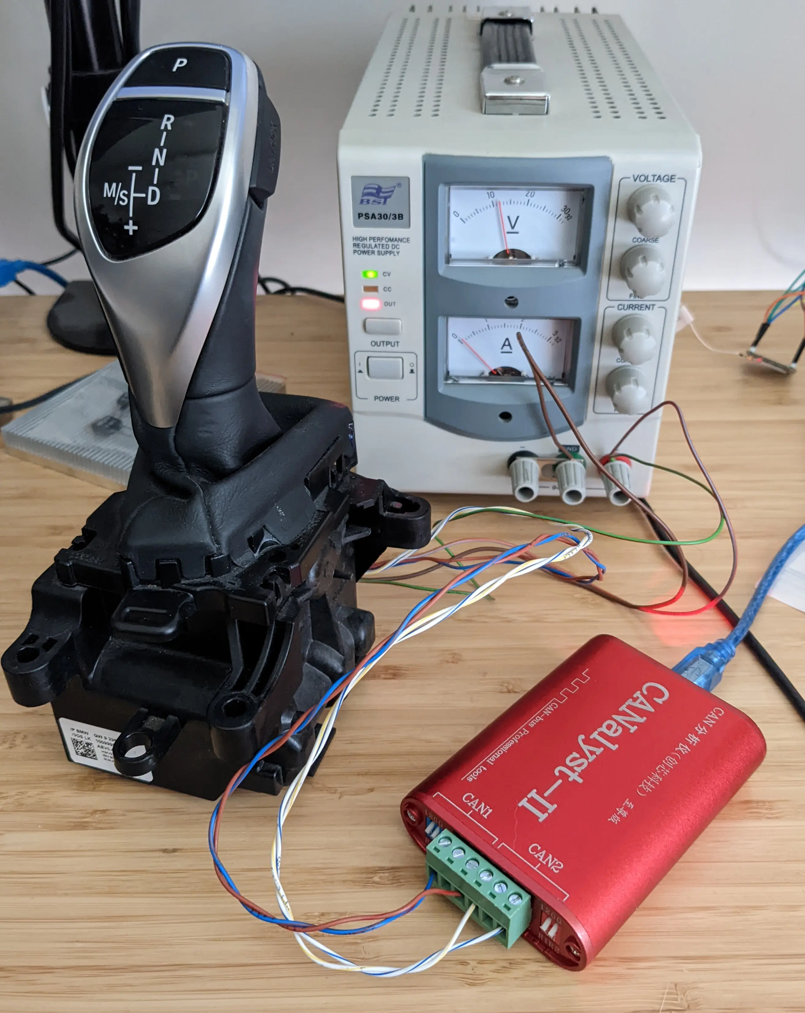
Connecting up all the known wires, no smoke came out... but nothing else either, no lights and no CAN messages. Current draw almost zero...
Looking on the PCB, mystery pin 7 (green/brown) was connected to what looked like a 51K/1.5K voltage divider. This seemed enough reason to try plugging it directly to 12V and check if it was an Enable or "Wake-up" signal. Sure enough, CAN messages immediately started transmitting on both buses at 500kbps!
CAN Output
This post doesn't include a primer on CAN protocol, there are a lot of good CAN introductions online including this short one. As a quick refresher, recall that each standard CAN message is up to 8 bytes of data with an associated ID that is either 11 or 29 bits long.
Looking at the CAN output, two regular messages showed up:
0x553 "Heartbeat" message
ID: 055e   00 00 00 00 01 00 00 5e
ID: 055e   00 00 00 00 01 00 00 5e
ID: 055e   00 00 00 00 01 00 00 5e
ID: 055e   00 00 00 00 01 00 00 5e
This message is sent every 640ms. The data payload doesn't seem to change over time.
Byte 4 of the message is 01 on "PT-CAN" and 02 on "PT-CAN2", so it provides a way to tell which bus you are listening to (and also confirms my guesses.)
0x197 "Selector Status" message
ID: 0197   85 08 0e c0
ID: 0197   0a 09 0e c0
ID: 0197   86 0a 0e c0
ID: 0197   09 0b 0e c0
ID: 0197   83 0c 0e c0
ID: 0197   0c 0d 0e c0
This shorter message is sent every 30ms on ID 0x197.
The first two bytes change on every message, and they are probably an in-message checksum and a "counter" value that other modules use to ignore accidentally repeated or "stuck" messages.
The third byte changes if you move the gear selector forward or back, and the last byte changes from c0 to d5 if you press the Park button. Pressing the "Unlock" button (needed in a real car to move out of Park or into Reverse) didn't change anything in this message. The gear lever also stayed locked from moving left to select "manual/sport shift" mode.
So I think this is the message that the GWS uses to indicate its position.
0x65e mystery message
I noticed a few other intermittent messages on ID 0x65e, with nearly identical data bytes but no clear timing or pattern:
ID: 065e   f0 10 0a 62 17 04 e0 94
ID: 065e   f0 10 0a 62 17 04 e0 94
ID: 065e   f0 10 0a 62 17 04 e0 94
ID: 065e   f0 10 11 62 17 04 e0 94
A burst of these 0x65e messages seems to be sent a short while after power-on, and then more bursts later at seemingly random times. We'll get back to those...
What next?
Applying power was enough to read the lever position, but the GWS itself is still blank - none of the LEDs for the gear modes have lit up:
There also is no way to tell if the driver pressed the "Unlock" button, or to let them select the "manual/sport" shift mode. So clearly there are some CAN messages the GWS is expecting to receive from the rest of the powertrain (probably the gearbox itself, maybe from other modules too.)
Best case, it needs to receive some valid control messages. Worst case, it has some "VIN locking" or "coding" in it that means it needs to see a car-specific sequence to start working at all.
The fastest way to figure this out is to have a full working car, to capture all the CAN bus traffic in a log to replay and analyse.
I've never even driven a BMW, so all I have is my lonely lever on the bench...
Failure 1 - Other BMW Selectors
I started by looking at some other BMW gear selectors that had already been documented by good people on the internet.
BMW E60
Damien Maguire, the undisputed champion of hacking EV parts into BMWs, had posted some notes on his BMW E60 gear lever's CAN messages:
(Photo courtesy "sheselectric" on the openinverter forums.)
E60 is an earlier generation than this F20 model, but looking at the gear selector you can see the family resemblance. Maybe BMW has reused the message IDs or formats? The E60 lever sends status on ID 0x198, this lever sends status on 0x197 - that seems hopeful, right?
No dice. Even sending variations on the E60 message IDs and the message payloads, my GWS continued to stare back at me blank and unresponsive.
OpenDBC E9x/E8x
The OpenDBC project is part of comma.ai's efforts to document the CAN message formats of as many cars as possible, particularly the driver assistance features. @dzid26 has a fork of this repo with some BWM E9x and E8x CAN messages.
You probably guessed already, none of these messages (or slight variations on them) got as much of a glimmer of response when sent to the GWS.
Internet Hunting
Obsessive internet searching didn't lead to much else. There is a BMW forum post by someone looking for the same info for an F30 model, but they had no luck. Someone did post a pinout that looked the same as mine - so that's encouraging.
I also found the forums for the PicoScope (a useful automotive debugging tool) had posted a short CAN capture from a BMW F31 to debug something else. Sadly, no likely looking messages in there.
Failure 2 - Random CAN messages
I retreated to the classic resort of the confused programmer: do random things and look at what happens.
It's possible to do a little better than sending purely random CAN messages: if one field in the message is probably a checksum, then it's possible to send a sequence of bytes where we increment one byte only each time and try all values 0x00 - 0xFF, then move to trying the next byte, etc, etc. For example:
00 55 55 55 55 55 55 55
01 55 55 55 55 55 55 55
02 55 55 55 55 55 55 55
[...]
fe 55 55 55 55 55 55 55
ff 55 55 55 55 55 55 55
55 00 55 55 55 55 55 55
55 01 55 55 55 55 55 55
55 02 55 55 55 55 55 55
[...]
This way, it's possible to send 8 * 255 = 2040 different 8 byte messages and know that at least one should have a valid 8-bit checksum in it, even without knowing which field is the checksum (provided the checksum is no more than a single byte, and doesn't span across two bytes in the message). I repeated this test with a range of possible CAN IDs, and then repeated again with some different data bytes (all 55, all 00, all FF, etc.)
Of course, as we saw above from the "status" message 0x197, the CAN messages may also contain a counter field. Sending random messages like this may not work at all if the GWS needs to see two messages with different counter values before it validates one of them. Also, of course, I have no idea if any of EE, 00, FF will be parsed as valid data values.
The worst part of this process was not having any automated way to check if something had happened. I was literally sitting and staring at the GWS in case it blinked an LED at me. I also tried automatically monitoring the current draw of the GWS, as I figured it would go up once it started doing things. However I wasn't sure if one valid message would spike the current enough to detect it.
This process... found something! Suddenly, the GWS lit up its backlight:

Replaying the messages around this value revealed message ID 0x202 would trigger illumination:
bus.send(can.Message(arbitration_id=0x202,
                     data=[0xFF] * 8,
                     is_extended_id=False))
Searching online turned up discussion that it's a common "Dimmer" BMW CAN ID used for this purpose, with only two meaningful bytes. The first byte is a brightness level:
brightness = 0x40
bus.send(can.Message(arbitration_id=0x202,
                     data=[brightness, 0x00],
                     is_extended_id=False))
So that's useful, but not what I was looking for...
Failure 3 - Find a real BMW
Getting a bit desperate, I started wondering about the ethics of renting a BMW so that I could capture a CAN log from it. I found a couple not that far away down in Melbourne... At the same time I wasn't sure this was a great idea, as you need to dismantle the interior a bit to access PT-CAN. It's probably a violation of the rental terms to partially dismantle the car for no good reason...
I was very excited to hear that a friend had just now bought a BMW 1 series, but equally devastated to learn it was a late "E" model code not an "F". What's the point of buying a shiny car if it's the wrong shiny car for me? Boo.
Failure 4 - Zero Budget Side Channels
Did I give up now? Almost! I mean, Heck No!. That would be the sensible thing to do, but nothing about this EV project is sensible.
Instead, I started looking for ways to do passive side channel analysis on the GWS' XC2336B microcontroller. In my case, I was thinking differential power analysis - closely measure the power consumption of the chip under two different conditions (in my case, valid CAN message received vs invalid CAN message received) and use this as a feedback function to guess (or fuzz) valid CAN messages. I figured the CAN peripheral is probably programmed to ignore most CAN IDs, so the CPU and digital logic is likely to work for a different amount of time depending on whether it sees a valid CAN ID or an invalid one. If it's possible to measure the current draw over time, it might be possible to differentiate an ignored CAN ID from a valid one and maybe even an invalid checksum from a valid checksum.
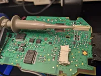
To start, I pulled the PCB out of the GWS and powered it up on my bench.
Then I looked long and hard at the datasheet for the XC2300 series microcontroller, particularly the power pins:
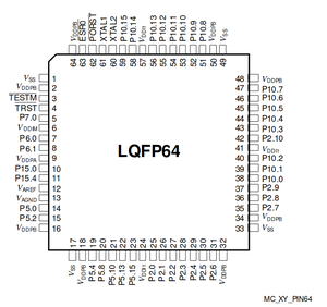
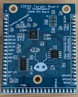
Some bad news, on the multi-layer PCB I could see no power trace that would be easily cut to isolate only the power consumption of the MCU. To measure full power consumption, the easiest method would probably be to make a dedicated carrier board, like a ChipWhisperer UFO target board. This lets you analyse the microcontroller away from the rest of the PCB:
I do have a ChipWhisperer Lite, but I wasn't ready to make a target board or desolder my only working GWS yet (coward).
Looking harder at the datasheet, I saw there are two internally regulated 1.1V "core voltage" power supplies (VDDIM and VDDI1) that require decent external decoupling capacitors:
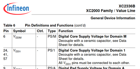
These power the core digital logic, including (I believe) the CPU. What if I removed the decoupling capacitors and monitored the voltage on this rail? Would the noise level allow me to tell the difference between "idle chip" and "chip doing something"?
This is pretty lo-fi, but lo-fi is all I need: I'm not looking to extract any actual data like an encryption key out of the chip (which is possible with "real" power analysis techniques). All I need is the difference between "the CPU is doing something" (like processing a valid looking CAN message) and "nothing is happening" (assuming the CPU spends most of its time in a wait-for-interrupt state or busy-looping).

Decoupling caps off:
I rigged up a small firmware (in Rust, woo) to send CAN messages and trigger the oscilloscope exactly after each new message was sent.
    loop {
        trigger.set_low().ok();

        if let Some(id) = try_read_id(usart1, &mut buffer) {
            if let Some(can_id) = StandardId::new(id) {
                let can_data: [u8; 8] = [0xFF; 8];
                let can_frame = Frame::new_data(can_id, can_data);

                /* Wait until gear lever has sent a
                    heartbeat and then a status, and then
                    immediately send our message (this is
                    to try and make sure the status of the
                    GWS CPU is consistent each time) */
                wait_for_can_frame(HEARTBEAT_ID, &mut can,
                    &timer, Milliseconds::new(1000))
                    .unwrap();
                wait_for_can_frame(STATUS_ID, &mut can,
                    &timer, Milliseconds::new(250))
                    .unwrap();

                // Note: this retries until it gets an ACK
                can.transmit(&can_frame).expect("Cannot send CAN frame");
                trigger.set_high().ok();
                defmt::trace!("sent CAN frame");
            } else {
                defmt::error!("bad CAN ID {}", id);
            }
        }
    }
And... nothing! The power rails remained pretty much rock solid, even with all the decoupling capacitors removed. Damn you, cautious and competent Automotive EEs!
Non-Starter: Reversing the firmware
Reversing the binary firmware seemed too hard. The XC2300 series MCUs have a "C166SV1 16/32-bit microcontroller core". As far as I can tell, this is the C166 16-bit CPU first released in 1990 but extended with some "32-bit extension" instructions to bring it into the 21st century. There are some open source C166 decoding plugins, but nothing that looks mature and nothing for these particular CPU extensions.
A friend of mine is reversing an automotive component with the Renesas V850 CPU architecture. Several smart and motivated people have been looking at that for over a year now, and they still only have part of it figured out. It's a big job!
Not to mention, I don't have the firmware binary and there's no debug pins on the board, or documentation for any debug protocol. Maybe there's an update file hidden in some proprietary BMW software somewhere, but this is also a pain.
So yeah, even I have limits of how far I'll go for a little gear lever...
End of the story?
The GWS continued to sit on my desk silently mocking me for a couple of months, until I got COVID.
More about that coming soon, in Part Two. In the meantime, please leave a comment if you have any ideas about what I could have done to glean the secrets of the GWS...
Please also comment if you like this style of "walkthrough reverse engineering failures", or not. I like reading this kind of thing, but if I'm the only one then I'll skip these details next time.
Thoughts on “BMW F Series Gear Selector, Part One: Failures”