Misappropriating discount store LEDs to improve the illumination in my microscope.
If "a poor workman blames his tools" then I am a poor workman when it comes to electronics. Every time I buy new equipment my soldering gets better - nicer soldering stations, different tips, decent magnification. Soldering under a microscope last year was a peek at the next step up - suddenly I could see the solder actually flowing into the joints, "wetting" and bonding to the surfaces.
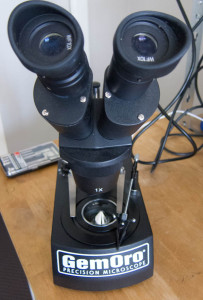
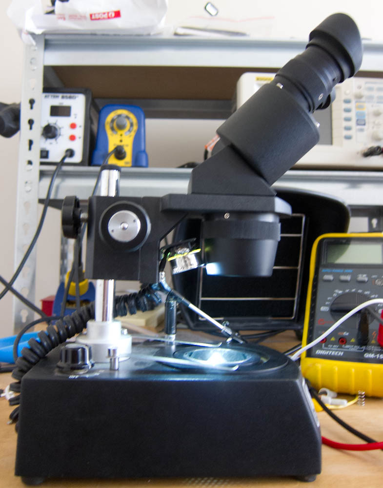
To further alleviate my poor workmanship, I was pretty excited to pick up a "GemOro Precision Microscope" from US ebay.

The GemOro Precision was sold in the late 90s as a gemstone microscope (here's a review) but its 10x and 30x magnification levels also suit a lot of electronics work.
There's just enough room to work under it with a soldering iron or a hot air tip, although it's not as roomy as a dedicated electronics microscope. For the low price I paid I'm very happy with it.
Illumination woes
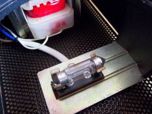
The biggest downside to the GemOro Precision are the incandescent 12V bulbs used for illumination (both the "stage" light from the top and the "sub-stage" light that backlights any slide you might be using.) Because mine is from the US it also only takes 110V mains power, not 240V.
This Saturday I decided to convert the GemOro to low voltage LED lighting.
Poor tools? Poor ingredients!
As this was a quick Saturday afternoon hack, I ran down to my local shops to see what LEDs I could obtain quickly at low cost. I came back with these two wonders of modern manufacturing:
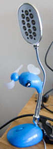
$2.50 Officeworks torch
This "mini torch" is sold by my local Officeworks office supply store for $2.50:
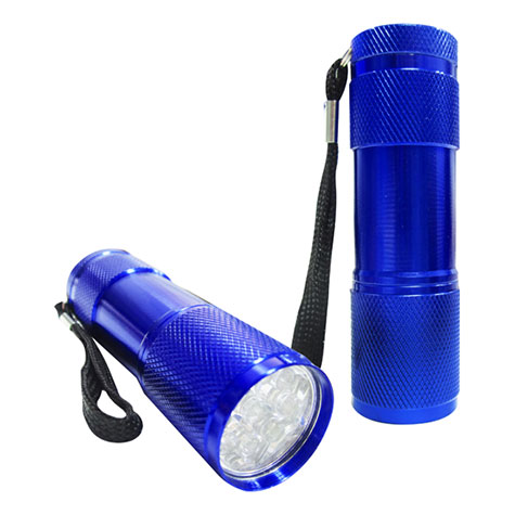
(Image courtesy Officeworks' web site.)
At my local electronics store one white LED costs $2.45, so by comparison this is a pretty good deal. For $0.05 more I get 9 additional LEDs, a reflector, 3 spare AAA batteries and a battery holder! Aren't economies of scale handy?
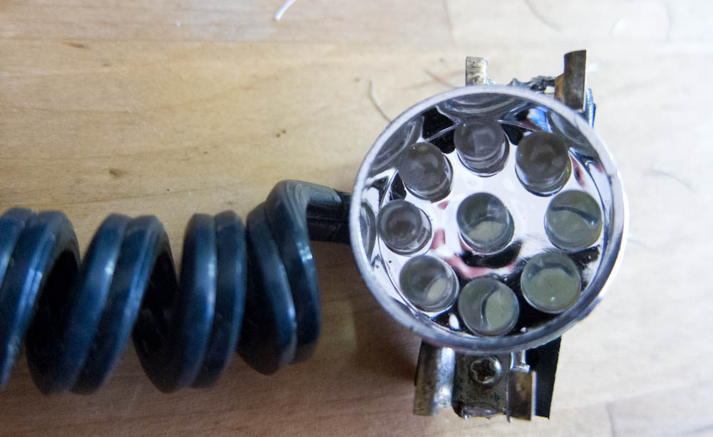
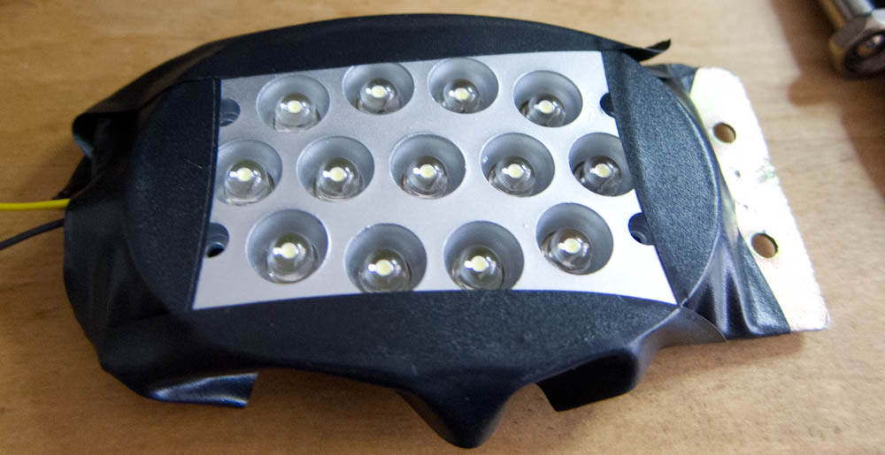
I used the LED cluster and reflector from the torch to create the "top of stage" downlighting.
$9 USB Lamp & Fan
This miracle of injection moulding, a USB powered lamp and fan, came from the local "discount store". I bought it in particular because I thought the fan might be useful for somehting. The fan wasn't useful for anything.
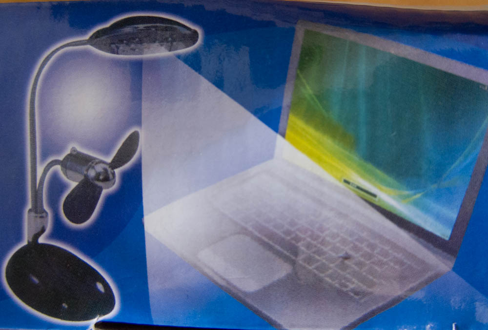
The USB lamp provided a donor USB power cable and a second LED cluster to create the "bottom of stage" backlighting.
Extracting useful bits
The LED torch proved to be pretty easy to disassemble, via careful application of a hammer:
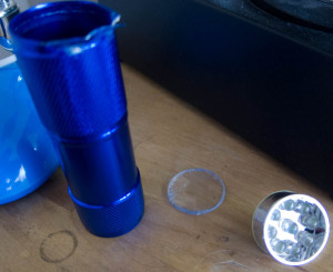
As the torch runs on 4.5V from its batteries I was hoping I could just reuse the circuit directly with 5V USB. However, there were no signs of current control inside. Seems most very cheap torches rely on the internal resistance of the batteries to limit the current flow through the LEDs. Not a good option when working from a USB port instead of a battery!
I needed some more information about the circuit, so I hooked up the LEDs and the battery pack. First I measured the forward voltage of the LEDs as 3.2V:
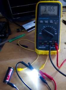
Then I measured the actual current flow:
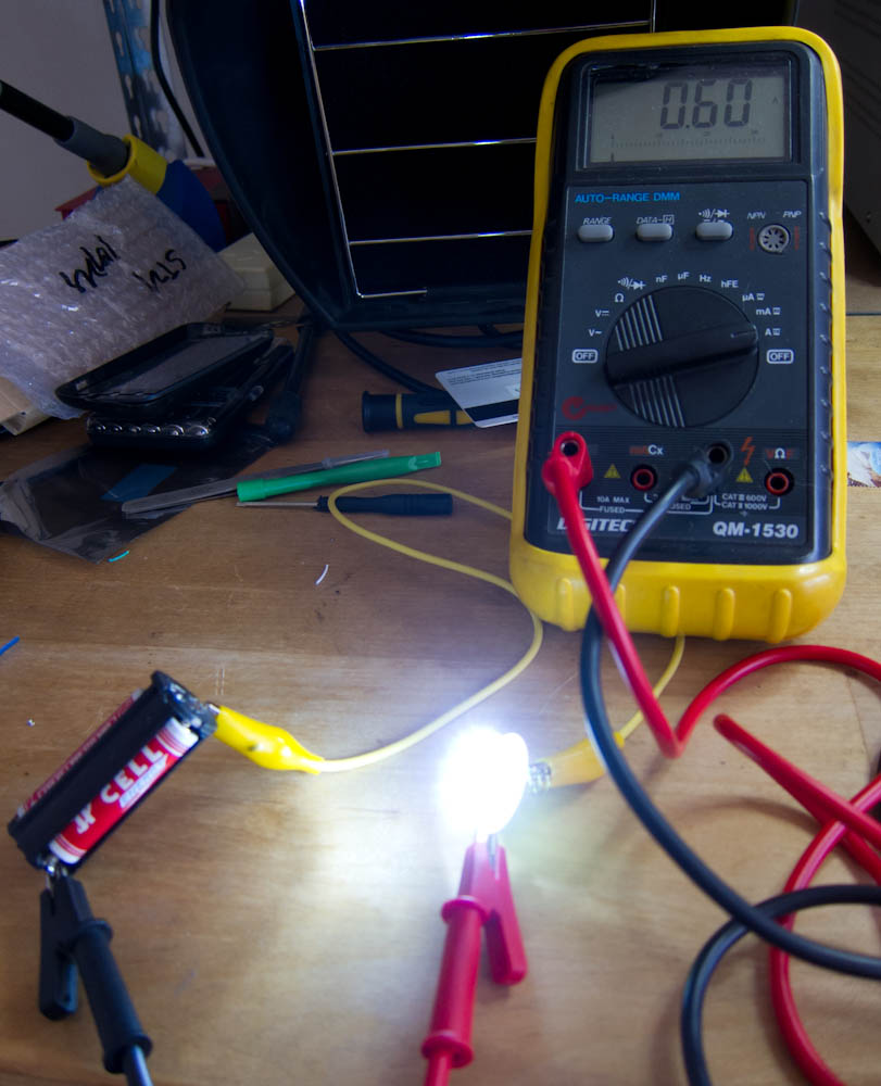
600mA, pretty substantial! This implies the 3 AAA batteries (which are wired in series) have about 720mΩ of internal resistance each ((R=V/I, R=(4.5-3.2)/0.6, R=2.2Ω over 3 batteries.))
(This random Alkaline battery datasheet suggests a internal resistance of 200mΩ for a charged AAA battery, making 720mΩ a fairly high internal resistance. Perhaps the internal resistance is going up to due to the high current draw? I wonder how rechargeable batteries survive in this kind of torch...)
I'd need a >1W resistor if I wanted to limit the USB current to the same 600mA. I only had 1/4W resistors in the house, so I soldered on this 1/4W 15Ω resistor instead:
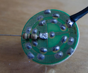
This yields a current of 110mA, which is still very bright. Probably better for the long term life of the LEDs, as well.
When it came to the USB lamp, things were a lot easier as the current limiting resistors were integrated on the LED Cluster PCB:
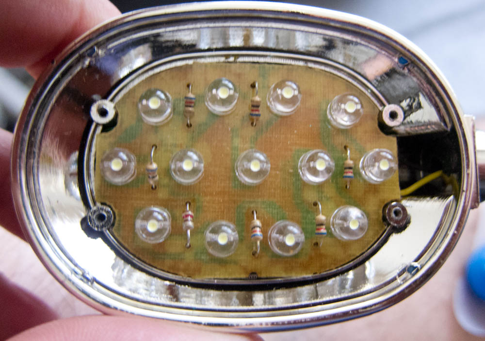
(Also worth noting that this design has multiple current limiting resistors, better than putting multiple parallel LEDs through a single resistor.)
Installing the LEDs
I employed several bodgy techniques to hold the LED clusters in place.
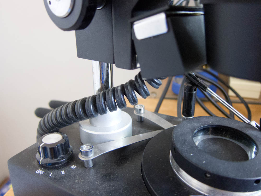
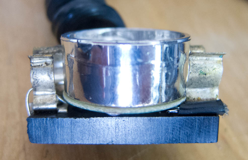
For the top light, I used the "blade" holder from the original 12V bulb to wedge it in (the blades doubled as electrical contacts):
For the bottom light, I took out the piece of metal that the original bulb had mounted to:

And used black electrical tape to first insulate the piece of metal, then strap the LED cluster to it:
We'll see how that goes long-term with heat...
After that, it was just a matter of bypassing the 110V->12V transformer and replacing the 110V cable with the USB cable from the lamp.
By reusing the existing 12V wiring I was also able to reuse the original switch.
Voila, a quick bodge!
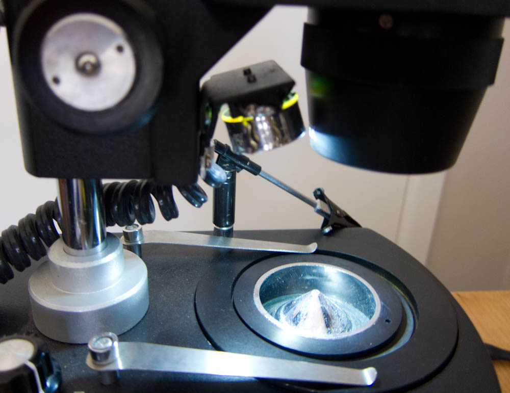
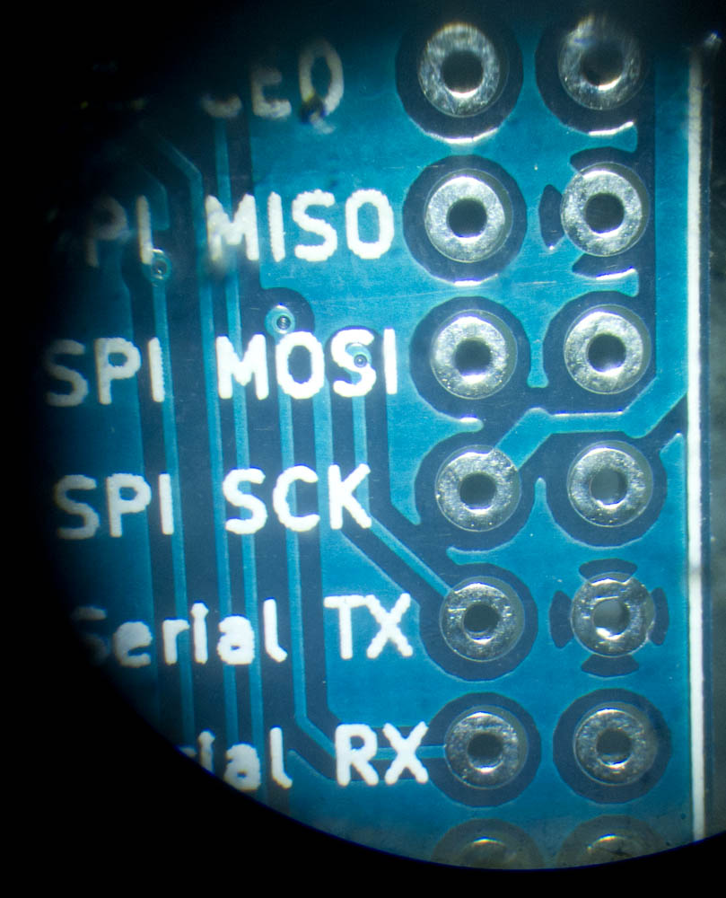
... I'm pretty happy with that for a quick Saturday afternoon hack. Despite its dodgy internals it looks pretty decent from the outside, and will hopefully last a while. The lighting is nice and uniform when inspecting a PCB.
Have you repurposed any discount store electronics lately?
Thoughts on “Hacked up LED Microscope Lighting”